BPMN-Centric and BPEL-Centric Edit Styles
Process Developer offers two edit styles for designing BPEL processes: Business Process Model and Notation (BPMN) and a BPEL-centric version of BPMN.
You can select the Process Editor Canvas edit style in Layout Preferences.
- •BPMN-Centric edit style includes the graphical notation elements described in the Business Process Model and Notation V2.0 standard.
- •BPEL-Centric edit style includes all BPEL constructs as well as some, but not all, graphic elements commonly used in BPMN modeling.
In both edit styles, every BPMN construct is serialized into a BPEL construct so that your process is 100% executable in BPEL.
New processes are associated with the edit style specified in Layout Preferences. Legacy processes are opened in the style they were created in.
For legacy processes, the original Process Developer Classic edit style is supported. For details, see What is Process Developer Classic Style?
What is BPMN-Centric Style
Business Process Model and Notation (BPMN) is a graph-oriented notation standard favored by business analysts and designers to model the flow of activities for analysis, documentation, and execution. According to the standard, BPMN creates a standardized bridge for the gap between business process design and process implementation. Also, BPMN aims to ensure that BPEL can be visualized with a business-oriented notation.
The BPMN 2.0 standard is governed by the Object Management Group (OMG).
Usage Rules for Shapes and Symbols
BPMN uses shapes, symbols, and connectors to represent constructs. The shapes, symbols, and connectors have standard usage rules and standardized operational semantics. BPMN also includes extensive annotation and documentation capabilities.
The main shapes are:
- •Rounded rectangle (activities)
- •Diamond (gateways)
- •Circle (events) with event-driven border styles (solid, thin, thick, dotted)
For a complete description of BPMN elements, see BPMN-to-BPEL Implementation of Tasks and Events and BPMN-to-BPEL Implementation of Gateways and Control Flow.
What is BPEL-Centric Style
BPEL-Centric style includes BPMN graphical notation to represent BPEL constructs. The BPEL palette contains the following notation:
- •Each BPEL construct is in the palette, except flow and sequence. These constructs are represented implicitly on the canvas for efficient process design. For example, if you drag a receive to the canvas, it is automatically enclosed in a sequence. When you add the next activity, it is automatically linked.
- •Some BPMN elements are included. To add visual clarity to a process, you can use the start, end, and none events and the fork-join and gateway control flows.
- •Some BPEL activities, such as a receive, can be shown in more than one BPMN construct. For example, a receive can be shown as a message catch event or a receive task. In the receive's Properties view, from the Show As list, select the BPMN display style.
Special Usage of BPEL and BPMN Constructs
The following table shows the BPEL constructs hidden and BPMN constructs used in BPEL edit style.
BPEL Construct Hidden in BPMN | BPMN Construct (not part of BPEL terminology) |
|---|
Flow (automatically embedded in a process design as applicable) | Fork Join |
Sequence (automatically embedded to structure a group of activities) | Gateway |
Opaque (not used) | Start/End/None |
See also:
- •Comparing the BPMN-Centric and BPEL-Centric Tool Palettes
- •Which Edit Style to Choose: BPMN-Centric or BPEL-Centric?
Comparing the BPMN-Centric and BPEL-Centric Tool Palettes
The following illustration shows the two palettes, followed by a discussion.
The following tables describe palette differences.
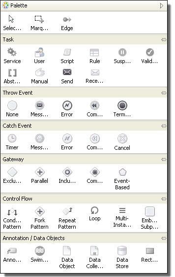
BPMN-Centric Palette
The BPMN-Centric palette is organized into the following groups:
Edges and selections | An edge connects two activities to make them run in sequence. Use the other selection tools to select a set of items on the canvas. |
Task | Basic process activities to build a process. For example, select a service task to represent a Web service endpoint. |
Throw Event | Events that have an impact (a result), such as a reply, invoke, throw, rethrow, compensate, exit, and break. These are outbound events. |
Catch Event | Events caused by a trigger, including wait, receive, and scope handlers, which include fault, termination, event, and compensation. These are inbound events. |
Gateway | Controls the divergence and convergence of sequence flows, including branching, forking, merging, and joining of paths. Includes the BPEL pick activity as an event-based gateway. |
Control Flow | Containers to structure a group of activities. |
Annotation/Data Objects | Add labels, shapes, and swimlanes to the canvas. They are ignored in the XML code, but they print. You can anchor a label to an activity. |
Custom | Save any activity or set of activities from a BPEL drawing as a custom activity. You can reuse the custom activity in other BPEL drawings. By default, the custom palette is hidden when empty. For details, see Creating a Custom Activity. |
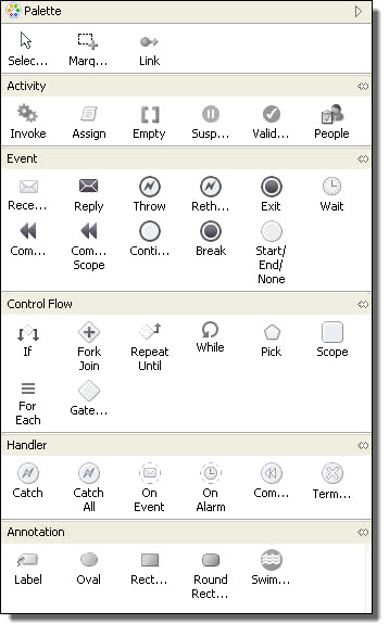
BPEL-Centric Palette
The BPEL-Centric palette is organized into the following groups:
Links and selections | Use a link to connect two activities to make them run in sequence. Use the other selection tools to select a set of items on the canvas. |
Activity | Basic process activities to build a process. For example, select an invoke to represent a Web service endpoint. |
Event | Select an activity that triggers an event, such as a receive, to start a process. |
Control Flow | Select a container or gateway to structure a group of activities. |
Handlers | Select a fault or event handler for a scope. |
Annotation | Add labels, shapes, and swimlanes to the canvas. They are ignored in the XML code, but they print. You can anchor a label to an activity. |
Custom | Save any activity or set of activities from a BPEL drawing as a custom activity. You can reuse the custom activity in other BPEL drawings. By default, the custom palette is hidden when empty. For details, see Creating a Custom Activity. |
See also: Which Edit Style to Choose: BPMN-Centric or BPEL-Centric?
Tips for using the palette:
- •By default, the palette is in auto-hide mode. Rest your mouse on the palette to open it.
- •Select the Show Palette or Hide Palette arrow to remove the auto-hide feature of the palette.
- •Right-mouse click on a palette group title to view a list of customization options.
- •Click on a palette group title to open or close the group.
- •Use drawing objects to annotate your BPEL processes.
- •Customize the palettes to view small icons or icons only. To view icons only, right-mouse click on any palette entry and select Layout > Icons Only.
Which Edit Style to Choose BPMN-Centric or BPEL-Centric
Which Edit Style to Choose: BPMN-Centric or BPEL-Centric?
Both BPMN and BPEL edit styles generate 100% validated, executable BPEL XML code. Both styles are diagramming notations for process descriptions. You can choose which visual style is easier for you and your team.
Highlights of BPMN-Centric
- •The edit style uses standard BPMN terminology.
- •The Process Developer break extension activity can be implemented with a terminate activity within a scope, for Each or while structured activity. The break implementation allows breaking out of the closest scope or loop.
- •The Process Developer continueextension activity is not supported because no notation in BPMN has the exact Continue semantics.
- •The error catch event is used for the catch and catch all fault handlers.
- •The error throw event is used for the throw and rethrow activities.
- •Annotations include icons for data objects, collections and stores.
- •An annotation can be linked to an activity.
- •A control flow structure, like a Conditional Pattern or Repeat Pattern, can be ungrouped into separate activities.
Highlights of BPEL-Centric
- •The style uses BPEL terminology for constructs and includes some common BPMN constructs. Not all BPEL constructs are visible. Some are hidden in order to produce a cleaner, clearer diagram.
- •The style includes the Process Developer extension activities break and continue
- •Catch and catch all fault handlers are represented separately
- •Throw and rethrow activities are represented separately
Using Swimlanes
You can provide a graphical representation of the participants in your process by adding a pool with swimlanes. The concept of a pool and swimlane is part of the BPMN specification. A pool represents a process and a swimlane represents a participant.
In Process Developer, you add swimlanes to the Process Editor canvas, typically to show each participant's activities. However, you can drag and drop activities into different lanes, using links to show the relationship between swimlane activities. There is only one pool for the process as a whole.
The following illustration shows an example of a process pool with four swimlanes, one for each process participant.
To add and use swimlanes:
- 1. Right-mouse click on the BPMN Editor canvas and select Add > Annotation > Swimlane.
- 2. Notice that a pool and one swimlane is created. The pool name is the process name, and the swimlane is untitled.
- 3. Do one of the following:
- - To add an additional swimlane to the left (or top) of the first one, right-mouse click on the left (or top) side of the process, and select Add > Annotation > Swimlane.
- - To add a swimlane to the right (or bottom) of the first one, right-mouse click to the right (or bottom) of the first one and select Add > Annotation > Swimlane.
- 4. To name a swimlane, select the swimlane titlebar and display Properties view. In the Text field, replace Untitled with your text.
If you want to change swimlane colors, you must first turn off zebra stripping.
Tips on working with swimlanes:
- •By default, swimlanes are displayed in bands of white and gray, called zebra striping. To disable zebra striping and enable individual colors for each swimlane, select the title bar of the pool and open the Properties view. Set properties as desired:
- •To delete a swimlane, right-mouse click on the swimlane and select Delete. Delete all swimlanes to delete the pool.
- •Swimlanes have only visual properties: You must manually arrange all activities within swimlanes.
- •You can add a swimlane from the Annotation drawer of the palette
- •Swimlanes can be used on the main canvas, not on the drill-down view of a collapsed container, nor on the fault or event handler tabs
Resizing Swimlanes
To make a swimlane grow or shrink, to accommodate the activities you add or delete, move a swimlane border either left or right in horizontal orientation (up or down in vertical orientation). By default, a resizing restriction is set on swimlanes to disallow a swimlane from being too small to accommodate an activity. The Restrict Swimlane Resizing property in the Pool is set to Yes. For flexibility in resizing a swimlane, set this property to No.
What is Guide Developer Classic Style
Process Developer Classic style is supported primarily for legacy processes.
Process Developer Classic uses the same palette of icons that has been in use since Version 1.0 of Process Developer. Each BPEL construct, as specified in the WS-BPEL 2.0 specification, is represented by an icon designed by Informatica. Because the BPEL specification does not include any requirements for graphical representation, each vendor who implements the specification creates their own look and feel.
In addition to representing BPEL constructs, Process Developer Classic, includes icons for the people activity, which is a Human Tasks extension. In addition, each style includes two Process Developer extension activities, break and continue.
In Process Developer Classic, the palette drawers are named Activity, Container, and Other.
BPMN vs. Process Developer Classic Style Examples
The following examples show some main differences between BPMN and Process Developer Classic styles.
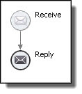
Example One: Shapes and Symbols
BPMN shapes have meanings. Circles indicate events, as shown with the receive and reply on the left below. Start events and end events have solid borders, while intermediate events have outlined borders. In Process Developer Classic, activities are categorized as basic and structured. Receives and replies are basic activities, represented by Informatica proprietary icons shown on the right.
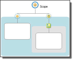
Example Two: Start, End, and Exception Events
BPMN uses event icons to indicate the start and end of a workflow (in BPMN terms a subprocess), as shown in the scope below on the left. The start and end events are within a hidden sequence container. You add activities between start and end. When you add a catch fault handler to the scope, the fault handler is displayed as a dotted rectangle within the scope. In Process Developer Classic, a scope starts out as an empty container. You display a fault handler with the Show Fault Handler option. Then you add a catch to it.
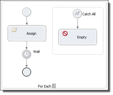
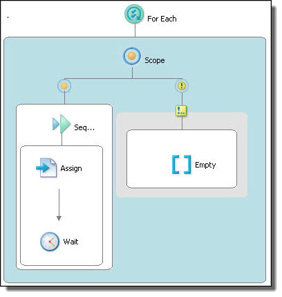
Example Three: Control Flow vs. Containers
BPEL often requires nested activities, such as those in a forEach, if, while, or repeatUntil. BPMN (on the left below) represents nesting with control flow arrows. In the forEach example, note also that the control flow contains an embedded (hidden) sequence. The sequence contains start and end events, and you can add activities in between. The start and end events are considered good style in BPMN, but are not strictly required, so they can be deleted if desired. Process Developer Classic displays a forEach container with an embedded, visible scope into which you add all activities manually.
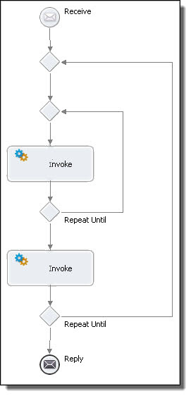
Example Four: Nested Activities
In BPMN, arrows represent control flow. Representing control flow using arrows can be easier to read than using containers, as shown in the example of nested repeatUntil activities. In this diagram, the parent repeatUntil has two children: a repeatUntil and an invoke. The child repeatUntil has one child: an invoke. The BPMN diagram is easier for many people to understand.