Using the Process Developer Process Editor
The Process Editor consists of a canvas and palette for creating a visual representation of a BPEL process. When you create a BPEL file, as described in Creating a New Process, the file opens in the Process Activities tab of the editor, and you have a canvas on which to create a process.
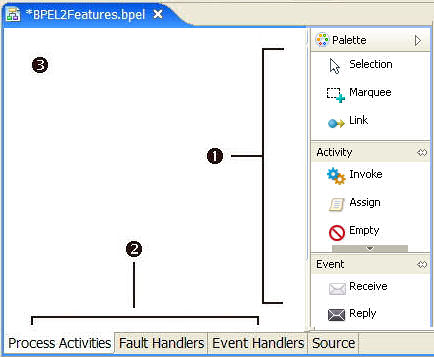
The following illustration shows the parts of the Process Editor.
1 | Palette. Select constructs to create a process definition. Annotate your process with drawing labels and shapes. Create custom activities to reuse in other processes. |
2 | Tabs. Select a tab to design a specific component of a process on its own page or to view the generated XML code in the Source tab. You can print the contents of each page. |
3 | Canvas. Drag palette items to the canvas. Set visual properties for the items and the canvas. |
Process Editor Process Activities Tab
From the Project Explorer you open a process file (a .bpel file), and the graphical representation of the process is displayed in the Process Activities tab of the Process Editor.
Some common activities using this tab are:
- •Use the Process Activities tab to design your process, including all activities, links, and structures. Select objects from the palette to design and annotate your process.
- •Use the Fault Handlers and Event Handlers tabs to design handling of exceptional events at a process level.
- •You can open as many .bpel files as you wish. Click on a file name in the Process Editor titlebar to display a specific process.
- •You can print the graphical elements on this page.
See also Tips for Designing on the Process Editor Canvas.
Process Editor Fault Handlers Tab
Use the Fault Handlers tab of the Process Editor to design process-level fault handling. You can add catch and catchAll containers and activities on this tab. These fault handlers are added to the <faultHandlers> section of the BPEL file.
Typical activities when using this tab are:
- •Adding scope-level fault handlers, see Adding a Fault Handler for a Scope.
- •Adding drawing labels to fault handlers.
- •Printing the graphical elements on this page.
Process Editor Event Handlers Tab
Use the Event Handlers tab of the Process Editor to design process-level message and time-out events. For more information, see Event Handling.
Typical activities using this tab are:
- •You can add drawing labels to Event Handlers.
- •You can print the graphical elements on this page.
Process Editor Compensation and Termination Handler Tabs
One BPEL process can invoke another BPEL process. In this case, the invoked process is referred to as a subprocess, and can be handled specially. The subprocess is eligible for compensation and termination handling in the same way as a process scope. For details, see Creating a BPEL Process as a Service for Another BPEL Process
These tabs are as follows:
- •Compensation Handler tab. Use this tab when you enable instance compensation for the process. For more information, see Process Element and Properties.
- •Termination Handler tab. Use this tab when you enable termination handling for the process. For more information, see Process Element and Properties.
Process Editor Source Tab
Use the Source tab of the Process Editor to view the generated XML code for your process. The code you see is validated against the WS-BPEL 2.0 specification. For details, see BPEL XML Source and Implicitly Added Activities.
Process Editor Source Tab
Use the Source tab of the Process Editor to view the generated XML code for your process. The code you see is validated against the WS-BPEL 2.0 specification. For details, see BPEL XML Source and Implicitly Added Activities.
Setting Visual Properties and Using Your Own Library of Images
For all of Process Developer's activity icons, you can change the font size, colors, borders, and other visual properties.
In addition, you can change the activity icons to impart more meaningful visual representation for the type of process you are building.
You can set defaults for all processes, as described in Layout Preferences, or you can modify visual properties for individual processes and activities.
Here are some examples:
Example 1: Add a border, change font size for an activity
Example 2: Select your own images for activities by setting the Image Location property for each activity
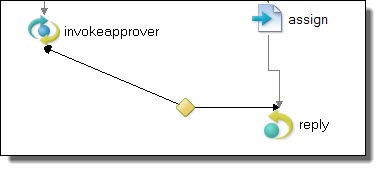
Example 3: Change the link router style from Manhattan to Manual
The manual style draws a straight link, rather than a stair-step style link, and allows you to set the angle for a link transition. A Shortest Path style link travels around the border of objects to link two activities.
The following table lists the visual properties you can set for various activities. Not all properties apply to all activities.
Property | Description |
|---|
Background Color | Fill color if the Transparent property is No |
Border | Yes/No selection to display a border on a drawing item |
Border Color | Opens a dialog for you to choose a basic or custom color for the border of a drawing item. |
Expanded | For a container, such as a Scope, a Yes/No display indicating whether the container's contents are displayed or hidden. This setting changes when you select Expand or Collapse from the container's right-mouse menu. |
Font | Sets the font to use for label. |
Font Color | Sets the color for labels. |
Image Display | The image to draw if any |
Image Location | Sets the file system location and name of the image file. See the Tips section below for multi-selecting activities to change their images. |
Image Text Gap | Select the size for the gap between an activity icon and the label. |
Label | Select the display format for an activity label. See Selecting Activity Labels. |
Label Alignment | Sets the align text property: left, right, center, top, bottom |
Label Placement | For a drawing object, sets the placement of text label relative to image. |
Location | Sets the the XY location on the canvas of the object |
Orientation | For a container, sets the vertical or horizontal orientation for activities within the sequence. |
Primary Alignment | For a Sequence activity, sets the alignment for the group of activities. |
Secondary Alignment | For a Sequence activity, sets the alignment position of the activities within the sequence. |
Size | Sets the the current size on canvas |
Size to Fit | Set to Yes to restrict resizing of the selected drawing object. Select No to permit resizing of the drawing object. |
Text | For a drawing object, text label |
Transparency Level | For a drawing object, sets the value of transparency. A larger value decreases the transparency. |
Transparent | Yes/No setting. If you select No, you can set the Background color. |
Tips for setting visual properties:
- •Set default values in a visual properties file. For details, see Layout Preferences.
- •For a particular process, to change the image for a group of activities, multi-select the activities and then select the Image Location. For example, select all receives to change the icon for that activity type.
- •To resize a container activity, such as an if activity, set the Size to Fit option to No.
Adding Tasks and Bookmarks to the Process
You can add a bookmark to a graphical element on the Process Editor canvas and create a link to easily jump back to that spot in the process. You can also add a task, which is similar to a bookmark. To add a task, highlight a graphical element and create a link to easily jump back to it.
A task is not related to the human interactions or people activity task element for a Human Tasks (BPEL for People) activity.
The difference between a task and bookmark is in the intent of the link. A task usually indicates something that needs to be done at that spot as opposed to just an easy link back to it. A task also has a priority to let you easily sort tasks by importance.
To add a task or bookmark to a graphical element, select the element and right-click. Select Add Bookmark or Add Task. Name the task or bookmark.
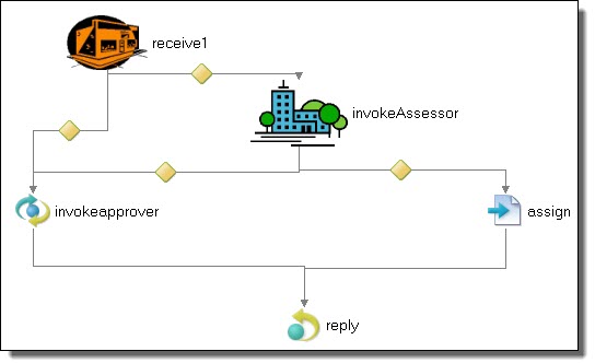
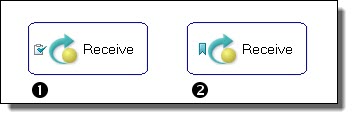
The following illustration shows a graphical element with a task or bookmark added.
1 | Receive activity with a task added |
2 | Receive activity with a bookmark added |
For more information, see Bookmarks View.
Adding Comments to a Process
Process Developer offers two ways to add annotations to a process: comments and documentation.
Comments are useful for design-time annotations because you can add tasks and to do items to them. They appear as HTML-formatted comments in the BPEL source code. You can also add a documentation element to a BPEL process, activity, and links. For details, see Adding Documentation to a Process.
You can add a comment to any element of the process, such as an activity, link, variable, or the process itself.
- 1. Select an item from the Outline view or the Process Editor canvas. For example:
- - Select Process or a partner link, variable, or copy operation from the Outline view
- - Select an activity or link on the Process Editor canvas
- 2. In the Properties view, at the end of the Comment row, click Dialog.
- 3. Type in a comment in the Comment dialog and click OK.
Tip: You can add a Task tag to the beginning of the comment and the comment appears in Tasks view. For details, see Tasks and Problems Preferences.
The comments for activities and links appear when your mouse hovers over them on the Process Editor canvas, as shown.
Comments appear as formatted tags in the Source view of your process.
If you want to add a comment about a namespace, add the comment to the process itself.
Adding Documentation to a Process
You can add one or more documentation items to the process or to an activity. If desired for language support, add a language identifier. The source field is for application-specific reference.
Process Developer offers two ways to add annotations to a process: Comments and Documentation. You can add a <documentation> element to a BPEL process, activities, and links. For design-time, comments are useful because you can add tasks and to do items to them. For details, see Adding Comments to a Process.
You can add documentation to any element of the process, such as an activity, link, variable, or the process itself.
If you generate a process report, the documentation is very useful. For details, see Generate Process Report.
- 1. Select an item from the Outline view or the Process Editor canvas. For example:
- - Select Process or a partner link, variable, or copy operation from the Outline view
- - Select an activity or link on the Process Editor canvas
- 2. In the Properties view, do one of the following:
- - Type text directly into the Documentation tab.
- - In the All view, at the end of the Documentation row, click Dialog (..). Complete the dialog as shown below.
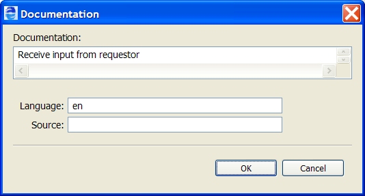
To fill in the Documentation Details:
- 1. Select New to open the Documentation Details dialog, as the example shows.
- 2. Fill in the dialog as follows:
- - Documentation. Enter the content in your chosen format, such as plain text, HTML, or XHTML.
- - Language (optional). Type in the language identifier of the natural or formal language that the content is written in. Refer to the XML 1.0 specification for language identifier reference details.
- - Source (optional). This attribute indicates the source of application information, in the form of a URI. (The attribute is described in the XSD schema and is generally included with the documentation element.)
- 3. Click OK, and select New to add additional documentation elements.
- 4. In the Documentation entries list, you can reorganize entries by selecting the Up or Down buttons. The first entry in the list is displayed in the Properties view of the activity, link, or partner link.
Documentation appears as formatted tags in the Source view of your process and also in a report that you can generate.
Tips for Designing on the Process Editor Canvas
Use the Process Editor canvas to create a graphical representation of a BPEL process.
Here are some tips for designing your process:
- •Double-click the Process Editor title bar to enlarge the canvas to full view.
- •Change the font size and color, borders, images and other properties for activities and links. See Setting Visual Properties and Using Your Own Library of Images.
- •Use the Auto Layout toolbar button to arrange process activities according to the settings in Layout Preferences. Use the Auto Layout option on the right mouse menu of any container or selection.
- •Use Make Vertical and Make Horizontal to change the orientation of your process.
- •When moving any activity or container, the object snaps to a grid. Use the Alt + mouse button to move an object one pixel at a time.
- •Use Zoom In and Zoom Out on the Process menu to change magnification of the canvas.
- •Select a Zoom percentage or Fit Page from the toolbar Zoom drop-down.
- •Use Expand or collapse containers to show or hide them. Drill down into a collapsed container to temporarily view its contents. See Showing and Hiding Activities.
- •Select two or more activities and link them using the Link toolbar button.
- •Use the Thumbnail View to view different parts of your process if it is large and complex.
- •Select two or more graphical elements and align them using the toolbar Align list.
- •Anchor a drawing label to an activity by selecting both and then selecting Anchor Annotation from the right mouse menu.
Showing and Hiding Activities
You can preserve Process Editor real estate in the following ways:
- •Expand and collapse container activities
- •Drill down into a collapsed container to temporarily see its contents
Expanding, Collapsing, and Drilling Down into Container Activities
You can collapse the display of container and control flow activities. These activities include sequence and flow (Process Developer Classic only), fork join (BPMN only), if, while, pick, scope, repeat until, and for each.
When an activity is collapsed, select the plus icon to temporarily drill down into the activity to view its contents. Use the bread crumb display or the Navigate > Back command to collapse the activity.
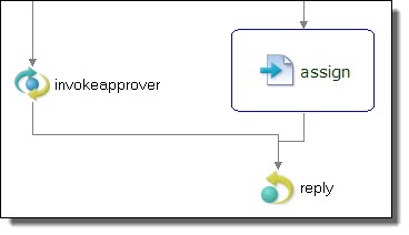
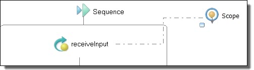
To collapse an activity, such as a scope, select Collapse Container (or Control Flow) from the right-mouse menu. The small icon, illustrated in the collapsed scope below, indicates the container is collapsed. To expand a container, select Expand Container (or Control Flow) from the right-mouse menu.
Tips for using Expand, Collapse, and Drill Down:
- •When an activity is collapsed, select the plus icon to drill down into the contents. Alternately, from the right-mouse menu, select Go Into Activity (Ctrl + Alt + L).
- •By default, the link style changes to a dotted line for a link with one or more targets in a collapsed container, as the example above shows
- •You can Expand All Containers and Collapse All Containers from the Process menu or from a blank spot on the Process Editor. Right-mouse select these options from the Process Editor.
- •You can set a preference to control the positioning of expanded and collapsed containers in relation to other activities. The setting affects the overall look of the process design. For details, see Layout Preferences.
- •You can Undo expand/collapse moves if you do not like the results
Process Editor Keyboard Shortcuts
The following tables describe how to select and move objects on the Process Editor canvas without using a mouse.
Navigation Keys
- •Navigate to a BPEL file in the Process Editor: CTRL + F6.
- •Navigate to a selected activity with the Go to Activity shortcut: CTRL + L.
See also Process Developer Menus and Toolbars.
Selecting an object
When an activity or container is selected, you can navigate to another object using the following keys.
Key | Action |
|---|
Space | Select |
Left arrow | Navigate to the object on the left |
Right arrow | Navigate to the object on the right |
Up arrow | Navigate to the object above |
Down arrow | Navigate to the object below |
/ or ? | Navigate to the next link |
\ or | | Navigate to the previous link |
Alt + Down arrow | Navigate into a container |
Alt + Up arrow | Navigate out of a container |
Pressing the CTRL key causes the focus, rather than the selection, to move. Pressing the SHIFT key while using one of the navigation keys extends the selection.
Moving an object
When an object is selected, you can move it using the following keys. Note that you can move an object diagonally by selecting two adjacent arrow keys simultaneously.
Key | Action |
|---|
Alt + mouse | Move the selected object one pixel at a time |
Period | Select next handle |
> | Select previous handle |
Left arrow | Drag left |
Right arrow | Drag right |
Up arrow | Drag up |
Down arrow | Drag down |
Enter | Commit the drag operation |
Esc | Abort the drag operation |
Palette Keyboard Actions
Key | Action |
|---|
Left arrow | If focus is on an expanded palette group, such as the Activity group, then collapse it. Otherwise set focus on the group. |
Right arrow | If focus is on a collapsed palette group, then expand it. If the group is expanded, then the focus moves into the group. |
Up arrow | If the focus is inside a group, then it moves to the group title. |
Down arrow | Moves to the next item |
Process Developer Function Keys
The following function keys are available.
Location | Key | Function |
|---|
Debug View | F6 | Step Over |
Debug View | F8 | Resume |